Best Interchangeable Cores
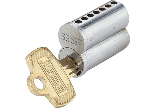
There are at least nine types of commercial lock cylinders: (1) key-in-knob or -lever, (2) rim, (3) mortise, (4) profile, (5) oval, (6) tubular, (7) wafer, (8) large format interchangeable cores, and (9) small format interchangeable cores. In this blog post I will discuss the components of small format interchangeable cores (SFIC) and their functions.
The SFIC or “key removable” system is the brainchild of Frank Best. It gets its name from the fact that a key, called a Control key, is used to remove a cylinder from a lock. This system is popular among facility managers because it allows them to quickly and easily rekey a lock in the event of a security breach or employee turnover. Since Best first introduced the interchangeable core (I/C) system in 1919, other lock manufacturers have followed in his footsteps and introduced their own I/C systems. These competitors included, but are not limited to: Arrow, Falcon, Kenstan, Medeco, and KSP.
The four primary parts of the SFIC cylinder are the (1) plug, (2) control sleeve, (3) core shell, and (4) plug retainer. Every SFIC plug is broached to accept a particular key profile and has five, six or seven chambers, with seven being the most widely used today. Its diameter is slightly smaller than that of a standard universal cylinder and is drilled at the back to accept two round pins found in a cylinder housing or the tailpiece used in a lever- or knobset.
The control sleeve accepts the plug. The plug rotates inside the sleeve to operate the lock. The sleeve has a rib or lug which is rotated 15 degrees to the right (clockwise) using the Control key in order to remove the cylinder from the lock. The lug is responsible for holding the cylinder inside the lock during normal operational use.
The core shell or cylinder case accepts the sleeve. The face of the shell forms the distinctive figure-eight design of all SFIC cylinders. The top and bottom portions of the shell are the same diameter. Ejector holes are milled into the bottom of the shell directly below each chamber so that the pins, springs, and caps can be pushed through the top of the shell using an ejector tool during the repinning or recombinating process.
The plug retainer is either a c-clip or a riveted circular plate found at the back of the plug. This clip or plate holds the cylinder together. It also forms the stop or tip gauge for the control and operating keys.
All SFIC cylinders have two shear lines. The shear line between the plug and the sleeve is called the “Operating Shear Line”, and the shear line between the sleeve and the shell is called the “Control Shear Line”. The former allows one to operate the lock, and the latter allows one to remove the cylinder for repinning and servicing.
A typical SFIC cylinder contains four types of nickel-silver or hardened stainless steel pins: (1) bottom or key, (2) master, (3) build-up, and (4) top or driver. The key pins are cone shaped at the bottom and flat at the top. The cone shaped end allows for easy key insertion and the flat end prevents master pins from rolling inside the chamber. Key pins come in ten lengths (0-9).
Master pins are flat at both ends. Spool shaped master pins can be installed however, to increase a cylinder’s pick resistance. Master pins come in 19 pin lengths (1-19).
Build-up pins are shaped like master pins. They create a shear line that is solved by the control key. They make the removal of the cylinder from the lock housing possible.
Top pins are shaped like build-up and master pins. They complete each pin stack and are critical to the proper operation of the cylinder. If these pins are too long, the springs may be damaged, the caps may be ejected, or a key with shallow cuts may not be able to enter the cylinder. If these pins are too short, the pin stack may not be able to rise to a level that will block the control shear line in a key with deep cuts.


